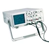
Detail OMEGA Benchtop Oscilloscope BOS Series
• 20 to 60 MHz Dual Trace, ALT Trigger
• Vertical Sensitivity: 1 mV/ DIV
• Horizontal Resolution: 10 nS
• Hold-Off, X-Y Operation, Z-Mod, Y-Output
• 23 Calibrated Ranges, Main Time Base
The BOS Series comprises dual-channel oscilloscopes with frequency bandwidths of 40 to 100 MHz at -3 dB, a maximum sweep of 10 ns, a maximum sensitivity of 1 mV/ DIV, and 150 mm rectangular CRT with internal graticule.
These oscilloscopes are rugged, easy to operate, and highly reliable. They are ideal for research, production, and electronics applications. The BOS converts a high-input differential voltage ( d1300 Vp) into a low voltage ( d6.5V) .
Optional accessories include differential voltage probes, which provide a safe means of measuring a floating potential.
Models BOS-200 BOS-205 BOS-350 BOS-355 BOS-605
Cathode Ray Tube 6" diagonal, rectangular screen with internal graticule 8 x 10 DIV ( 1 DIV = 1 cm) , B31 phosphor, 2 kV acceleration voltage 6" diagonal, rectangular screen with internal graticule 8 x 10 DIV ( 1 DIV = 1 cm) , B31 phosphor, 12 kV accel voltage
Vertical Deflection
Bandwidth DC to 20 MHz ( -3 dB) DC to 40 MHz ( -3 dB) DC to 60 MHz ( -3 dB)
Sensitivity 1 mV/ DIV to 1 V/ DIV ( 5 MHz, -3 dB) , x5 gain selected 5 mV/ DIV to 5 V/ DIV 1 mV/ DIV to 1 V/ DIV ( 10 MHz, -3 dB) , x5 gain selected 5 mV/ DIV to 5 V/ DIV 1 mV/ DIV to 1 V/ DIV ( 15 MHz, -3 dB) , x5 gain selected 5 mV/ DIV to 5 V/ DIV
Attenuator 1-2-5 sequence, 10 step with variable control
Input Impedance 1 M© ± 2% , 25 pF ± 10%
Max Input Voltage 400 V ( DC + AC peak)
Rise Time About 17.5 ns About 8.8 ns About 5.8 ns
Overshoot Less than 5%
Operation Mode CH 1, CH2, DUAL ( ALT, CHOP)
Algebraic Addition CH 1 + CH 2, CH 1 - CH 2
Inverter CH 2 Only
Horizontal Deflection
X-Y Mode Switch slectable using X-Y switch; CH 1: X axis, CH 2: Y axis
Accuracy X Axis: ± 6% , Y Axis: ± 3%
Bandwidth DC to 1 MHz ( -3 dB)
X-Y Phase Difference Approx. 3 degrees at 50 kHz
Sweep System
Sweep Display Mode Main, Mix Main, Mix, Delay Main, Mix Main, Mix, Delay Main, Mix, Delay
Hold-Off Time 5: 1 continuously variable
Main Sweep
Sweep Speed 0.1 ? s/ DIV to 2.0 s/ DIV in 1-2-5 sequence, 23 steps
Accuracy ± 3%
Variable Time Control 5: 1, uncalibrated, continuously variable between steps
Sweep Magnification 10x, ± 10% , extended sweep speed up to 10 ns/ DIV
Delay Sweep
Sweep Speed 0.1 ? s/ DIV to 2.0 s/ DIV in 1-2-5 sequence, 23 steps 0.1 ? s/ DIV to 2.0 s/ DIV in 1-2-5 sequence, 23 steps
Accuracy ± 3% ± 3%
Sweep Magnification 10x, ± 10% , extended sweep speed up to 10 ns/ DIV 10x, ± 10% , extended sweep speed up to 10 ns/ DIV
Delay Timeposition Variable control to locate desirable waveform for extending Variable control to locate desirable waveform for extending
Triggering
Trigger Coupling AUTO, NORM TV-V, TV-H AUTO, NORM TV-V, TV-H
Trigger Source CH 1, CH 2, ALT, LINE, EXT CH 1, CH 2, ALT, LINE, EXT
Slope ± ±
Trigger Sensitivity
Coupling TV-V, TV-H, Auto, Nom
Bandwidth DC to 1 kHz, 1 kHz to 100 kHz , 100 Hz to 20 MHz, 100 Hz to 20 MHz
Interior 1.0 DIV, 1.5 DIV, 1.0 DIV, 0.5 Vp-p
Exterior 0.5 Vp-p
Dimensions 324 W x 398 D x 132 mm H ( 12.75 x 15.67 x 5.20" )
Net Weight Approx. 7.6 kg ( 16.75 lb)
Rated Range of Use 10 to 35° C ( 50 to 95° F) , 10 to 80% RH
Component Test
Test Voltage Max 6 Vrms ( open circuit) Max 6 Vrms ( open circuit)
Test Current Max 11 mA ( shorted) Max 11 mA ( shorted)
Test Frequency Line frequency Line frequency
Components Capacitor, inductor, diode, transistor, zener, etc. Capacitor, inductor, diode, transistor, zener, etc.
CH 2 Output
Output level 100 mV ( no load) , 50 mV/ DIV ( with 50 © load)
Bandwidth 20 Hz to 20 MHz 20 Hz to 40 MHz 20 Hz to 60 MHz
Graticule Illumination Adjustable
Calibrator Square wave about 1 kHz, 2 V p-p ± 3% Square wave about 1 kHz, 2V p-p ± 3%
Z-Modulation Positive TTL signal, low-level blank intensity at any intensity, high-level unblank any intensity Positive TTL signal, low-level blank intensity at any intensity, high-level unblank any intensity
Trace Rotation Adjustable on front panel Adjustable on front panel
Power Source 110 to 130V ( 800 mA fuse) , 200 to 260V ( 600 mA fuse) 50/ 60 Hz selectable
Power Consumption Approx. 38 W
Limits of Operation 0 to 50° C ( 32 to 122° F) , 10 to 80% RH
Storage Environment -30 to 70° C ( -22 to 158° F) , 10 to 90% RH
Tampilkan Lebih Banyak